Objective:
To design and fabricate manual baling machine to make silage.
Need of the project:
Silage is nutrient-rich fodder which is obtained by compactly storing green fodder in airtight conditions. Generally, it is made in large bags of capacity 500 kg or more.
The baling machine that we will be making will be used to make silage in relatively small bags of capacity 10 to 15 kg. A class 2 type lever arrangement will be made which will have a mechanical advantage of 4 i.e. if a force of 100N is applied at the free end that force will be multiplied by 4 and we will get 400N as a load on the green fodder for compacting.
Selection of bag for the machine:
Requirments from the bag:
- It should be waterproof,
- It should be durable i.e. The bag should have sufficient strength for repetitive use.
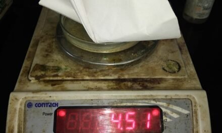
We looked for options based on the above two conditions and finally zeroed down on coated polypropylene bag.
Bag dimensions:
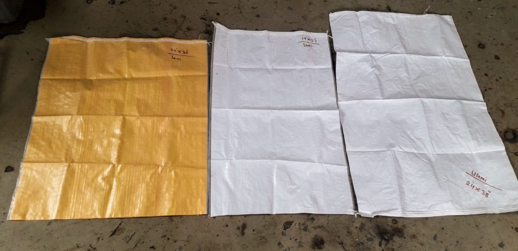
We had 3 bag dimensions to choose from 24*30, 19*33 and 24*38 (all sizes are in inch). We selected 24*38 square inch since it was better suited for use.
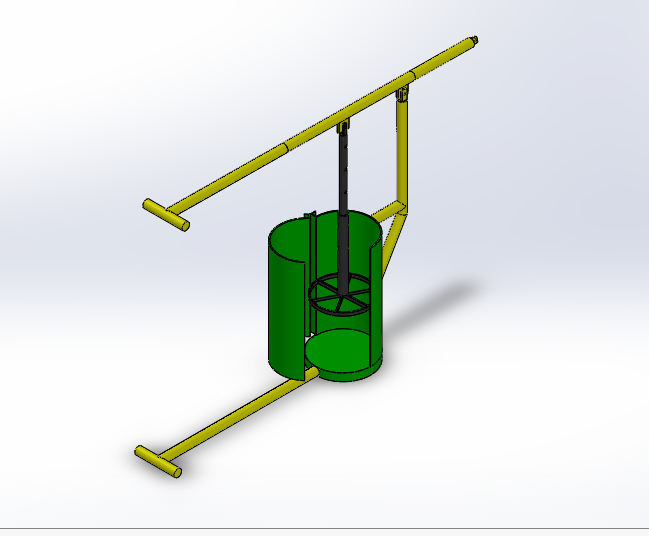
Design of the machine:
Before the actual designing of the machine could begin, we had to determine the dimensions of the material that we were going to use for the construction of the machine. The main body of the machine will be fabricated using only 2 types of material. One is a hollow metallic pipe and the other is a metal sheet for the drum.
Out of the two, the determination of pipe dimensions was the most important since it was going to be under the most stress.
Calculation to determine diameter of pipe:
Calculations were done considering an applied force of 981N ( considering a person weighing 100Kg would apply the force). We have also used dimensions of GI pipe available at the ashram with OD=41.56 mm and ID=37.14 mm for the sack of calculations.
While drawing the free body diagram of the class 2 lever we have chosen the dimensions arbitrarily just for the sake of reference.
Calculation of reactive forces:
Considering equillibrium of the vertical forces,
i.e Summation of all vertical forces=0,
therefore,
-981-Ra+Rc=0………..(1)
Also equating the moment about point A to be equal to zero,
therefore,
(-Rc*0.4) + (981*1.6) =0…………….(2)
on solving equation 2 we get, Rc= 3924 N.
putting this value in equation 1 we get,
Ra = 2943 N.
Calculation of SFD and BMD:
To calculate Shear forces we have considered the following sign convention,
RUN= Right up negative,
LUP = Left up positive,
RDP = Right down positive and
LDN: Left down negative.
In section AC,
Shear force= -2943N
In section CB
Shear force= 981 N.
To calculate bending moment we have considered the following sign convention,
Sagging bending moment= Positive,
Hogging bending moment= Negative.
bending moment in section AC, at a section ‘x’ mm away from end A
= (-2943)x (Nmm)……..(3)
At A, x=0 mm hence
bending moment at A =0.
At C, x=400 mm hence
bending moment at C = (-2943)*400 =-1177200 Nmm.
bending moment in section CB, at a section ‘x’ mm away from end B,
= (-981)x Nmm……(4)
at point B, x=0 mm hence ,
bending moment at B=0
at point C, x=1400 mm hence,
bending moment at C = (-981)*1400 =-1177200 Nmm
Calculation of bending stress:
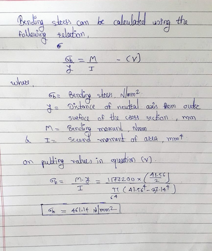
Keep in mind that for calculating I- Second moment of area, we are using Outer diameter=41.56mm.


